Start Up or Shut Down "Time Remaining"
This example will allow you to put a Timer object on your Crestron touchpanel that displays the time remaining in a Stepper sequence. This is useful for a startup or shutdown "time remaining" indicator. This example is for a 2-series processor. As always, no SIMPL+ is required.
This logic is all fully scalable. As you insert new logic into your stepper, all of the values will be dynamically recalculated. This logic works for any sequence shorter than 600 seconds (ten minutes). If your sequence is longer, you'll need to use the time hi-word and do some additional math.
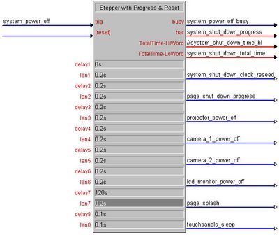
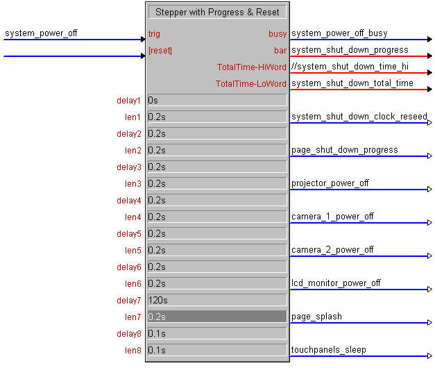
1. The first step is to insert a Stepper with Progress & Reset (STEPPER2) symbol. Populate the delays, lengths, and outputs with all of the events for your sequence. In this example, it is a shut down sequence. If you need to "pad out" some time at the end (i.e. waiting for a projector to power down) just insert a dummy step with the amount of time necessary.
You will need the busy signal, the bar output, and the time loword. You can comment out the time hiword, since we are limiting our logic to 600 seconds or less. You also need the first step to be a "reseed" step, which we will use to reset our countdown clock later on.
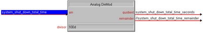
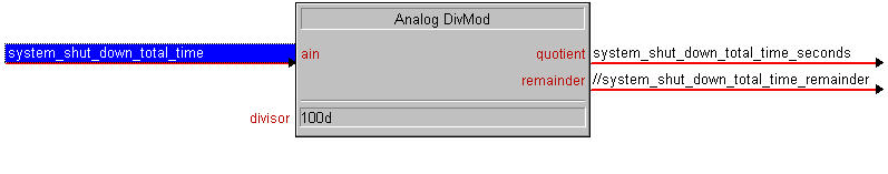
2. We need to scale the time down from 1/100ths of seconds to just regular seconds. We'll use an Analog DivMod (DIVMOD) symbol to do this. Take the total time loword value from your Stepper2, and tie it to the input of a DivMod. The divisor will be 100d, since we need to divide by 100. The quotient will be the number of seconds your entire countdown sequence will take. The remainder can be commented out.
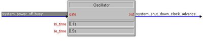
3. The next step is to setup a trigger to advance the clock as the stepper runs. We'll use an oscillator (OSC) for this. The trigger is the busy signal from the Stepper2. The output signal will be used to advance the clock. The hi_time should be 0.1s, and the lo_time 0.9s.
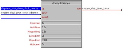
4. We'll now insert our logic to actually modify our clock. We'll use an Analog Increment (AINC). The up input is not needed and can be commented out. The down input will be trigger by the output of our Oscillator. The output is the analog signal for our countdown timer on the touchpanel. Tie this to your touchpanel, and create a Timer object in Vision Tools.
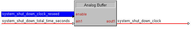
5. Finally, we need logic to set the clock to the beginning value when our countdown begins. An Analog Buffer (ABUF) should be inserted. The enable will be the reseed value from the first step of our Stepper2. The input is the total time in seconds that is provided by our DivMod. The output will be the actual countdown analog signal. This is the same signal that is on the output of the Increment, and is tied to the touchpanel's timer object. The increment is 1d, because we want the timer to advance by one second at a time. The hold time and repeat time really aren't important, so set them to 0.5s each. The lower limit is 0d, and the upper limit is 600d (because the only values our timer will display are between 0 seconds and 600 seconds (10 minutes)). The mute level is also not important and can be set to 0d.

This logic is all fully scalable. As you insert new logic into your stepper, all of the values will be dynamically recalculated. This logic works for any sequence shorter than 600 seconds (ten minutes). If your sequence is longer, you'll need to use the time hi-word and do some additional math.
1. The first step is to insert a Stepper with Progress & Reset (STEPPER2) symbol. Populate the delays, lengths, and outputs with all of the events for your sequence. In this example, it is a shut down sequence. If you need to "pad out" some time at the end (i.e. waiting for a projector to power down) just insert a dummy step with the amount of time necessary.
You will need the busy signal, the bar output, and the time loword. You can comment out the time hiword, since we are limiting our logic to 600 seconds or less. You also need the first step to be a "reseed" step, which we will use to reset our countdown clock later on.
2. We need to scale the time down from 1/100ths of seconds to just regular seconds. We'll use an Analog DivMod (DIVMOD) symbol to do this. Take the total time loword value from your Stepper2, and tie it to the input of a DivMod. The divisor will be 100d, since we need to divide by 100. The quotient will be the number of seconds your entire countdown sequence will take. The remainder can be commented out.
3. The next step is to setup a trigger to advance the clock as the stepper runs. We'll use an oscillator (OSC) for this. The trigger is the busy signal from the Stepper2. The output signal will be used to advance the clock. The hi_time should be 0.1s, and the lo_time 0.9s.

4. We'll now insert our logic to actually modify our clock. We'll use an Analog Increment (AINC). The up input is not needed and can be commented out. The down input will be trigger by the output of our Oscillator. The output is the analog signal for our countdown timer on the touchpanel. Tie this to your touchpanel, and create a Timer object in Vision Tools.
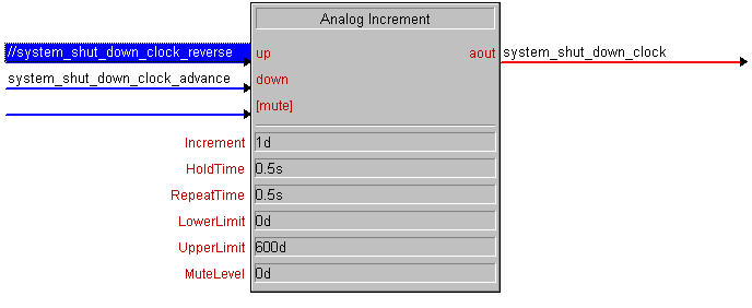
5. Finally, we need logic to set the clock to the beginning value when our countdown begins. An Analog Buffer (ABUF) should be inserted. The enable will be the reseed value from the first step of our Stepper2. The input is the total time in seconds that is provided by our DivMod. The output will be the actual countdown analog signal. This is the same signal that is on the output of the Increment, and is tied to the touchpanel's timer object. The increment is 1d, because we want the timer to advance by one second at a time. The hold time and repeat time really aren't important, so set them to 0.5s each. The lower limit is 0d, and the upper limit is 600d (because the only values our timer will display are between 0 seconds and 600 seconds (10 minutes)). The mute level is also not important and can be set to 0d.
posted by IP Wrangler at 11:08 PM
![]()
![]()
0 Comments:
Post a Comment
<< Home