A request was made in the Crestron discussion forum for some help with parsing strings in SIMPL+. For this example, we're going to use the protocol for an Autopatch matrix switcher. Two good things about Autopatch - a) The protocol is the same across all of their products, and b) operations done from the front panel create the exact same command strings as those sent across the RS232 connection. For part 1 of this example, we're going to work with responses to the Autopatch route command, which comes in this format: "CLxIyOzT". In this case, x represents the "level" being switched - for a basic audio/video switcher, x represents a route on the audio level, 2 the video level, and 0 represents an audio follow video route. y represents an input, and z the output. T - for "take" is the delimiter used by Autopatch to represent the end of a command. For example, the string "CL2I3O4T" coming in the com port tells us that the switcher has just routed only the video (level 2) from input 3 to output 4.
Let's assume that we've already got a program going that uses the autopatch BCS protocol to initate routes. We've now been tasked with the requirement that we obtain feedback from the unit to acknowledge our commands AND let us know if a user has simply gone up to the front panel of the switcher and manually done a route. So given the strings coming in from the switcher, we want a set of analog values in our SIMPL program to reflect which input is currently routed to which output. We want both audio and video status, as our system application calls for the possibility of breakaway routes. For the sake of simplicty, we're going to say that we're using an Autopatch half-Y 12x4 switcher. That leaves us with the need to create 8 analog signals in our SIMPL program - 4 for audio, 4 for video.
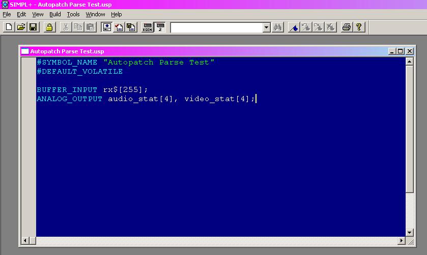
To start out - in SIMPL, we'll go File -> New SIMPL+. When the SIMPL+ editor appears, we want to select File -> New -> New SIMPL+ Module. In the window that comes up, just go ahead and delete all the text, and add these lines:
#SYMBOL_NAME "Autopatch Parse Test"
#DEFAULT_VOLATILE

BUFFER_INPUT rx$[255];
ANALOG_OUTPUT audio_stat[4], video_stat[4];
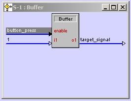
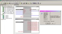
aside from coloring, your screen should look something like this:
If we go ahead and save this file as Autopatch Parse Test, then select Build -> Save And Compile, (or just hit F12) you'll see that our four-line module is A-ok as far as the compiler is concerned:

You can now pop back over to SIMPL, open your Symbol Library pane, expand User Modules, then -- All User Modules --, and you'll be able to drag Autopatch Parse Test into your logic folder. Double-click it from there, Alt-Plus all the outputs, and now you can drop all the signals you want from your SIMPL program, and even go ahead and compile it!
As you can see, your program is ready to load right this second if you wanted. You don't have any added functionality yet, but the point is that you can get your S+ module to a point where it can be integrated into your SIMPL program VERY easilly - if for no other reason than to have points to "land" all the signals you need from the SIMPL program onto the module. (I tend to do this when creating modules - before adding any real code to them - in order to make sure I've declared ALL of the signal connections I need to bring in from and take back out to SIMPL)
We're about to add some functional code to our SIMPL+ module, but let's just look at the few lines we have already:
#SYMBOL_NAME is simply a constant - this is the name that eventually appears in your Symbol library.
#DEFAULT_VOLATILE - this means "when I declare a variable for storage, use memory from the processor's large available pool of volatile memory, not the limited amount of non-volatile memory". We won't get into the volatile/non-volatile discussion here - suffice it to say that any variables we declare will not retain their value through a power outtage. In this case, (and IMHO, most) this isn't a problem.
BUFFER_INPUT rx$ - this one is special. Any strings coming in from your SIMPL program on this input will be qued up in a buffer. Power outtages aside, these strings will stay in there until we deliberately remove them, or the buffer fills - in which case the oldest characters in the buffer will be deleted in order to make room for new ones.
ANALOG_OUTPUT audio_stat[4], video_stat[4] - with these two declarations, we're telling the SIMPL+ compiler that our symbol will have 8 analog signals going back into our SIMPL program. As you've already seen on the symbol in the SIMPL environment, these are "arrayed" - I.E., with one signal name and a number in hard brackets, we've told the compiler that we want that number of outputs, each with the same name, but with an index ranging from 1 to the number we've chosen.
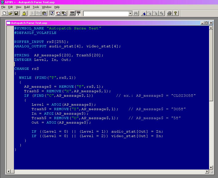
Let's go ahead and add some variables and lines of code to our module:

I'm going to try to break these down as quickly as possible, but there's a lot here of importance:
STRING  AP_message$[20], Trash$[20];
INTEGER Level, In, Out;
These are variable declarations. We're telling the compiler to create two containers capable of holding 20 characters (Think SIMPL serial signals, attached to MSPs) and three containers for numerical data - just like analog signals in SIMPL.
CHANGE rx$
A key point in our module. This indicates an "event handler" in SIMPL+. By specifying rx$ - the point where a serial signal feeds into our module from SIMPL - we're saying "Any time SIMPL passes data to our module on rx$, run the following block of code". In SIMPL+, blocks and sub-blocks of code are designated with curly brackets.
WHILE (FIND("T",rx$,1))
In SIMPL+, the FIND command takes the string specified in the first parameter and checks to see if it exists in the string specified by the second parameter. We can tell it how many characters into the string we want to start looking at with the third parameter. In this example, we always want to start looking from the very first character in the string, so we leave this set to "1". If the target string exists, FIND will tell us (by returning an integer value) how many characters into our source string we have to go before finding it. If the target string is NOT found, FIND returns a zero. The WHILE keyword says "as long as the following condition is TRUE, run the associated block of code. In SIMPL+, an integer value can be used in a true/false evaluation - anything other than zero is considered a "true" value, while zero represents false. We put the two of these together to create a statement that basically says "As long as the letter T exists in the buffer that has just been fed by the SIMPL program, run the following block of code".
If you think about that statement, you'll probably realize that we BETTER make sure that we do something to remove any Ts we find from the buffer, right?
The way the CHANGE / WHILE /FIND is structured is important - the SIMPL program will pass some characters into our rx$ buffer without any guarantee that there happens to be a letter T there. The case of a user walking up to the front panel of an Autopatch is a perfect example. Assuming they've already selected just the video level button for routing, as they press the following sequence of buttons:
Input 3 button
Output 4 button
Take button
The crestron com port will see:
CL2I3
O4
T
Our CHANGE rx$ block of code will "fire off" three times at a minimum here, and the block of code following the WHILE/FIND statement will only be executed once! If we assume that rx$ contains nothing to start with, here is what rx$ becomes with each successive button press on the Autopatch - don't forget that rx$ "buffers" characters!:
Input 3 button -> Crestron gets "CL2I3", passes that to our module -> rx$ now equals "CL2I3"
Output 4 button -> Crestron gets "04", passes that to module -> rx$ now equals "CL2I3O4"
Take button -> Crestron gets "T", passes that to module -> rx$ now equals "CL2I3O4T"
ONLY on that third "event" will the FIND statement evaluate to TRUE, in turn telling the WHILE statement that the following block of code should be run.
AP_message$ = REMOVE("T",rx$,1);
The REMOVE keyword takes parameters exactly like the FIND keyword does. In the case of the REMOVE keyword however, we are now saying "Starting at character 1 of rx$, REMOVE all of the characters up to and including the T and store them in the variable AP_message$.
If you're paying attention, you'll now realize that with our current example, rx$ no longer has a T in it, so when this current block of code is done, the WHILE/FIND statement will be re-evaluated, determined to be false, and the entire block of code for the CHANGE event handler will be considered completed. If we neglected to use this REMOVE command, the WHILE statement would never evaluate to false, and the code would just keep looping over and over again. (Yes - that's bad)
NOTE: While this may never be the case for an Autopatch switcher, we've coded the WHILE/FIND statement in such a way that if by SOME chance two or more Autopatch commands - ending in a T - come into our module in one shot, (maybe our Pro2 was taking a coffee break) we're still taken care of. IMHB (In My Humble Belief) your CodeKarma gets extra points for doing this for every module, for every device you're collecting data from. For other devices that send out a LOT of data very quickly, and/or instances where the code running in our CHANGE event might take some time to process, we would need to worry about and handle the possibility that our CHANGE event handler could be triggered multiple times - before it has had a chance to complete the first batch of processing. For this example we won't worry about it, but if the day comes that your SIMPL+ code seems to not be processing data correctly, you'll want to look into this.
But I dirgess - where were we? Ah - we just placed the contents of our buffer - up to the first letter T found in it - into a variable called "AP_message$". The next line may seem curious:
Trash$ = REMOVE("X",AP_message$,1);
Why are we looking for a letter X in our AP_message$ variable, which we know only contains "CL2I3O4T", and putting everything up to and including it into a variable called Trash$? Well, in this case that line doesn't do much of anything - X doesn't exist in our variable, so there's nothing to remove and nothing to put in Trash$. But... (you knew there was a but, right?) Some Autopatch units have a cancel button on them. If a user starts to enter a route sequence, then changes their mind and wants to start over again, they hit the cancel button, which puts a letter X in the response going to the processor. Here's an example sequence:
Input 2 button
Output 1 button
(user here says "aww crap - I meant to do 3 to 4")
Cancel button
Input 3 button
Output 4 button
Take button.
Guess what - right there rx$ would equal "CL2I3O1XCL2I3O4T". Our code doesn't activate until it sees a T in there, remember? Our code would now put all of this into AP_message$. We don't want or need any of the characters up to and including when the user hit the cancel button, so we simply "throw them in the trash" ($) Now we're back to having AP_message$ = "CL2I3O4T". Next!
IF (FIND("C",AP_message$,1))
Not all messages from the Autopatch start with a C. This line makes sure that the ONLY message we're going to attempt to parse is one that has a C in it, and ends with a T. (At least until we get to Part 3 of this example) :)
Okay, so FIND did find a "C" in our message, and we should run the associated block of code, which starts with:
Level = ATOI(AP_message$);
The ATOI keyword stands for "ASCII to Integer". It will take the string you point it to, and will START looking for a valid number among the characters. Assuming it finds a number, it will STOP when it no longer sees characters that make up that number, and then assign the (pay close attention here) numerical/integer value represented by the characters making up that number to the INTEGER variable "Level". In the string "CL2I3O4T", ATOI will skip the "C", the "L", then start paying attention with the "2". The next character after the 2 isn't a number, so it puts the INTEGER value of 2 into our variable Level and lets the next line of code run.
Trash$ = REMOVE("I",AP_message$,1);
We have the first number from our message - the level associated with the route - so we no longer care about any of the characters up to and including the I. Throw 'em out! AP_message$ now equals "3O4T".
In = ATOI(AP_message$);
If you're following all this, you'll realize that after this line, the integer variable "In" will now be equal to 3.
Then we lose everything up to the "O" in the string, do ATOI one last time to get the numeric value of the output from the route and place it into variable "Out".
I hope at this point that the last two lines are fairly intuitive. The first line translates to "If this route was on level 0 or 1, (it was either an audio follow video or an audio only route) take the ANALOG OUTPUT audio_stat associated with the the output number we found in the message, and assign the value of the input to it. The second line does something similar, only it looks for a condition that indicates a video level route has taken place, and puts the correct number on the correct ANALOG OUTPUT.
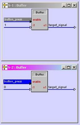
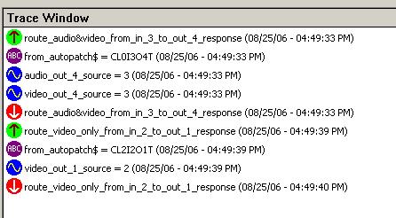
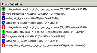
For testing, we've set up a couple of SIO's in our SIMPL program that pretend to be an Autopatch switcher responding to two routes:

Here's what Test Manager looks like when we trigger them:
Stay tuned for part 2...