Using Crestron to Select Sources for Multiple Destinations
fonze_scm asked for a suggestion on a method to allow users to select from multiple sources, select one or more outputs for a source, and then press a "Take" button to send the patches to all of the different display devices. Here is one suggestion, as always using only Crestron SIMPL Windows, without SIMPL+.
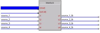
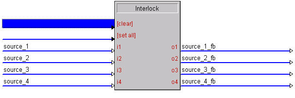
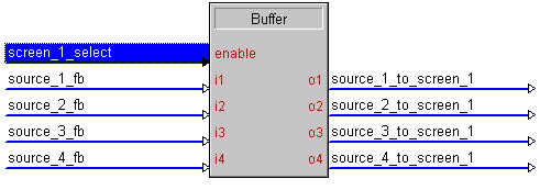
The first step is to provide a set of buttons on the touchpanels to allow the user to select the source they are going to assign. I recommend using an Interlock (IL) for this function. Name the inputs after your sources, and the outputs the same name with "_fb" at the end. These should be tied to the presses and feedbacks for the buttons on the touchpanel for each source.
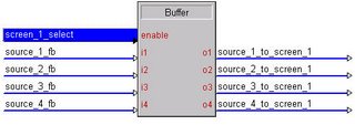
The second step is to draw buttons on the touchpanel for each of the outputs. Name the press and feedback for each of these buttons something like "screen_1_select." This press should be routed to the enable of a buffer. The inputs of the buffer should be the feedback outputs of the interlock, and the outputs should be signals such as "source_3_to_screen_1." This will pulse an output for the selected source, unique for the display, when the display is selected.
The user can easily route the same source to multiple displays by selecting the source, and then selecting each desired display.
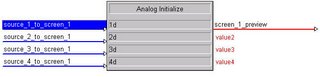
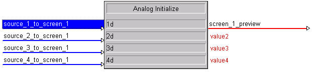
Next, insert an Analog Initialize (INIT) for each display device. This will convert the digital pulses from the buffers into an analog value for the "preview" source for each display device. Remember, fonze_scm doesn't want the Crestron system to route the source to the display device until the user presses a "TAKE" button.
Take the outputs from each buffer and route to the inputs of an analog initialize. The output should be named something to the effect of "screen_1_preview." This output will contain a value indicating the source that has been selected for preview.
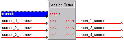
Finally, draw a "TAKE" button on the touchpanel. This will be assigned the signal name "execute" which will trigger an Analog Buffer (ABUF). The ABUF will take the sources that have been selected for each display, and send them to an analog variable containing the current source for each display device. This can then be processed using an Analog Equate (EQU) or other analog logic for sending the commands to the switchers and display devices.

If you want the inputs cleared after a patch is made, insert a stepper that clears the Interlock and/or Initiliazes after the TAKE button is pressed.
The first step is to provide a set of buttons on the touchpanels to allow the user to select the source they are going to assign. I recommend using an Interlock (IL) for this function. Name the inputs after your sources, and the outputs the same name with "_fb" at the end. These should be tied to the presses and feedbacks for the buttons on the touchpanel for each source.
The second step is to draw buttons on the touchpanel for each of the outputs. Name the press and feedback for each of these buttons something like "screen_1_select." This press should be routed to the enable of a buffer. The inputs of the buffer should be the feedback outputs of the interlock, and the outputs should be signals such as "source_3_to_screen_1." This will pulse an output for the selected source, unique for the display, when the display is selected.
The user can easily route the same source to multiple displays by selecting the source, and then selecting each desired display.
Next, insert an Analog Initialize (INIT) for each display device. This will convert the digital pulses from the buffers into an analog value for the "preview" source for each display device. Remember, fonze_scm doesn't want the Crestron system to route the source to the display device until the user presses a "TAKE" button.
Take the outputs from each buffer and route to the inputs of an analog initialize. The output should be named something to the effect of "screen_1_preview." This output will contain a value indicating the source that has been selected for preview.
Finally, draw a "TAKE" button on the touchpanel. This will be assigned the signal name "execute" which will trigger an Analog Buffer (ABUF). The ABUF will take the sources that have been selected for each display, and send them to an analog variable containing the current source for each display device. This can then be processed using an Analog Equate (EQU) or other analog logic for sending the commands to the switchers and display devices.
If you want the inputs cleared after a patch is made, insert a stepper that clears the Interlock and/or Initiliazes after the TAKE button is pressed.
posted by IP Wrangler at 11:38 AM
![]()
![]()
6 Comments:
Thanx! I have been reading the info and it is GREAT! Keep It up
-R-
I'm looking to pull off a similar scenario for a pad8a.
I'm stumped at the moment as this seems to work opposite for me and reproducing it the other way doesn't allow multiple zone selection. I would like to:
-select one or multiple zones that can be toggled.
-selecting one of the eight sources would route that source to those zones that are toggled to enable.
Any ideas?
Replying to the previous post:
I do this all the time for our Multi-Room applications.
It gives the client the ability to:
1. Turn on and off individual rooms
2. Choose weather those rooms should have control of source/volume
3. Allow different sources to be patched to different rooms.
The execution is fairly simple:
First
Create buttons that would be your power buttons. Usually i do this in VT pro by labeling the button with the room name (and making it pretty big!) In SIMPL, connect the room name to the Set of a Set/Reset Latch. Using a Press & Hold Symbol of about 2 seconds, connect the same room name to the input of the press and hold. The output should be the room name + "held". Connect this to the "reset" part of your latch. Connect the output of the set/reset to the room on the Pad8. (You can also connect the *out of the set/reset to logic that would detect when all rooms are off if you wanted to "de-trigger" amplifiers). You now have a button that when pressed the first time turns the room on. When held for 2 seconds, the room turns off. Any subsequent press for less than 2 seconds will have no effect on the room (The Room is already "set")
Using the same names that you used for the "set" input, connect it to the "toggle" input of a toggle command. The output can say "Dining Room Selected" and should be connected to a different feedback on the panel. (So if your room name is Dining Room and is Press 1, feedback 1 is from the Set/Reset Latch. Feedback 10 would be "Dining Room Selected" and the press would be commented out.) This sequence now will turn the room on, on only the first press, but will toggle the room being "selected" or not on each subsequent press. The output of this toggle should then be fed to the enable of a buffer. This buffer is where you have all you source and volume commands. When the "Dining Room" is selected, any press of volume or source will effect that room. You can rinse and repeat, and "viola" you have a virtual, client oriented, patch bay. Hope this helps!
Hello, great resource this, well done its the only independent Crestron resource I can find on the web!
Can you explain how Crosspoint routing works? Or even better can you give an example program?
I've done the intermediate course but this remains the only issue that I do not fully undertstand....thanks in advance
djivor
Post a Comment
<< Home