It is important to understand the way that memory is allocated in a SIMPL Windows program. vdonr posted a message asking about this on the Crestron Yahoo! message boards on June 22nd, and a lengthy thread developed. This post contains a summary of the advice given about the use of NVRAM (Non Volatile Random Access Memory) on the Crestron processor. Credit is given at the end to the many contributors.
NVRAM is used to store data in the Crestron processor in the event of a processor reboot (such as a power outage, a crash or a program upload). The common symbols used for this are Analog RAM, Digital RAM, Serial RAM, and SIMPL+ variables that have been flagged as non-volatile. There are other symbols as well (such as Analog Non-Volatile Ramp), but these are the basics.
In SIMPL+, only variables that have been flagged as non-volatile are stored when the processor reboots. By default, SIMPL+ inserts a #DEFAULT_NONVOLATILE (on line 25 if you are using the default template). This directive will store all variables that are not specifically flagged volatile in NVRAM. If you replace this directive with #DEFAULT_VOLATILE, all variables that are not specifically flagged non-volatile will not be stored in NVRAM, freeing up memory space. There is a decrease in speed when accessing non-volatile variable in SIMPL+, so this should be avoided unless necessary.
One common mis-conception is that the symbol Make String Permanent (MSP) has something to do with NVRAM. It does not. The MSP is used to make "transient" serial strings permanent. The primary reason to do this is to ensure that the strings are sent to a touchpanel when it issues an update request. There are also cases in SIMPL logic where a "permanent" string is desired.
Another important thing to remember is that NVRAM and NVRAMDISK do not necessarily mean the same thing. NVRAM is the non-volatile memory of the Crestron processor. NVRAMDISK refers to the practice of partioning a certain percentage of this memory for use as disk space. This allows a programmer to write data to disk without a compact flash card present. The use of compact flash or NVRAMDISK can avoid a lot of the problems typically associated with the use of NVRAM symbols like the Analog RAM.
NVRAM is addressed from the top of the program to the bottom. While it is not necessary to know exactly how much memory is consumed by each symbol during normal programming (as the compiler handles it for you), it will make it easier to understand the allocation process if we spell out the memory consumption in bytes of each symbol.
The Analog and Digital RAM symbols use 4 bytes of memory per input/output pair, multiplied by the number of selects declared. So, an Analog RAM with five inputs and outputs and two selects will use 40 bytes of NVRAM ((4 x 5) x 2).
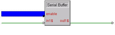
The Serial RAM symbol uses 1 byte of memory, plus 1 byte of memory per character used, all multiplied by the number of selects declared. So a Serial RAM with 24 characters specified and three selects will use 75 bytes of NVRAM ((1 + 24) x 3).
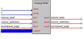
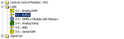
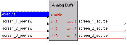
In the following example, we have an Analog RAM with two inputs and outputs and a single select, a SIMPL+ module that uses some NVRAM, and a Serial RAM with 24 characters and two selects.
The first Analog RAM symbol would use the first eight bytes of memory (two inputs/outputs x 4 bytes per input/output = 8 bytes.) The SIMPL+ module will use the next memory slots (the number of bytes of NVRAM that are indicated at compile time.) The Serial RAM will use the next 50 bytes ( (1 + 24 characters) x 2 selects = 50).
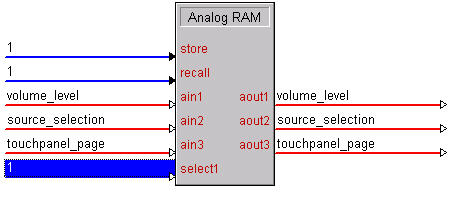
If we insert an extra input/output pair at the end of the Analog RAM, the next time we upload every symbol after that (the SIMPL+ module and the Serial RAM) will have their data "corrupted" by the changes in memory addresses. The Analog RAM will now take up the first 12 bytes of NVRAM, not just 8 like it did before. So, the SIMPL+ module will be starting at the 13th byte of NVRAM, not the 9th. The first four bytes of the Serial RAM will now be in the addresses that the SIMPL+ is looking at, the each byte of the Serial RAM will be "shifted up" four bytes, probably rendering all of the data useless. All of this data will have to be re-stored at the touchpanel. If the program were larger, this could be a big headache.
Another way to jumble up the memory would be to insert an NVRAM symbol somewhere above any other NVRAM symbol, or to change the order of the NVRAM symbols. This would have the same effect, as memory is addressed from the top down.
I consider the following to be "best practices" when dealing with NVRAM in a Crestron program:
1. Change the compiler directive in SIMPL+ modules that you write to #DEFAULT_VOLATILE, unless you know that you need almost all of the variables to be stored after a reboot for some reason. Flag individual variables as non-volatile as needed. (example: "NONVOLATILE INTEGER x;")
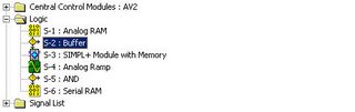
2. When you're writing a program from scratch, put all of the NVRAM symbols (including SIMPL+ modules with non-volatile variables) at the top in a dedicated sub folder. When you add NVRAM as you are working, put it at the bottom of this sub folder. Do not change the order of these symbols. This way, whenever anyone modifies your program in the future, none of your data will be corrupted.
3. When you're modifying someone else's program, place any new NVRAM symbols at the very bottom. This way, you know you will not be corrupting any of the original data.
4. Avoid NVRAM use in modules, as this encourages the NVRAM to fall elsewhere in the program.
5. Store large arrays of data (such as camera location presets, phone numbers, user names, etc.) to NVRAMDISK or Compact Flash. This avoids problems with memory addressing altogether. Things like volume are usually OK in NVRAM, because it doesn't take a long time to re-enter the data in the event that the value is corrupted. Using Compact Flash is ultimately the best choice, as it can be accessed by multiple SIMPL+ modules simultaneously.
6. If your top folder contains multiple NVRAM symbols, and you're storing a lot of information in a single Analog RAM, add a few extra lines with dummy signals at the end. This way, if you need to expand the Analog RAM, you can just comment one of these back in and rename it, without corrupting the memory allocation.
This is a summary of a number of posts on the Yahoo! group by: al_avt, alan_audiblesolutions, andyross94928, bfschroe, bryn4ne, chipmoodydcs, ckangis, ipwrangler, lkingcliby, m_ras, mjrtoo2000, richard_leek, skaudle, thatkirk