Ethernet Intersystems Communications
If you need to share resources between two Crestron processors, Ethernet Intersystems Communications (Ethernet ISC) is the way to go. This allows digital, analog and serial signals to be sent from one Ethernet-equipped processor to another, and vice versa. Ethernet ISC is also sometimes referred to as "XSIG over Ethernet," as it takes the place of the original symbol XSIG that was used to connect two Crestron processor via RS-422 or RS-232. Ethernet ISC is supported by all Crestron Ethernet cards, including CNXENET and CNXENET+ cards.
In our example, we will have a PAC2 processor that is used for lighting control, and a PRO2 processor that is used for audio/video control. The Cresnet network of the PAC2 processor will have some C2N-DB8 keypads, on which two buttons are used for lighting control (within the PAC2 program) and six buttons are used for selecting a source and controlling the volume for the audio system. Our PRO2 processor will be at 192.168.1.101, and our PAC2 will reside at 192.168.1.102.
The first step is to get the two processors onto the network, and test to confirm that they can communicate with one another. Assign each an IP address, and make sure you can ping one from the other. Use the Viewport or Toolbox command prompt command PING. (in our example: "ping 192.168.1.101" from the command prompt while connected to the PAC2 should reply "alive") If you can't ping the processors from one another, Ethernet ISC will not work.
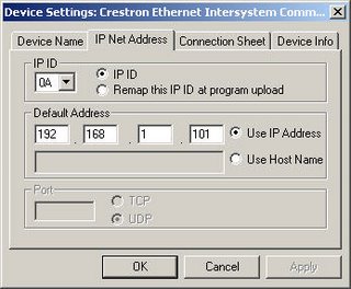
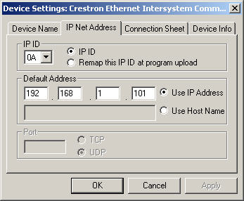
Second, we will insert an Ethernet ISC definition underneath the network card in each processor. To do this, open the Configure view in SIMPL Windows, open the Network card, and double-click on an available IP-ID. Select Ethernet Intersystems Communications from the list. The two definitions must be at the same IP-ID in order for communications to be established. We will use the IP-ID 0A. Each processor's IP table entry will contain the IP address of the opposite processor. So, the PRO2 will have the PAC2's IP address (192.168.1.102) and the PAC2 will have the PRO2's IP address (192.168.1.101)
IP Table setup for PRO2:

IP Table setup for PAC2:
At this point we should upload our programs and check to make sure that Ethernet ISC connection is up. Be sure to upload both programs, and say YES to sending the default IP table. To check our Ethernet ISC, we can type EST at the command prompt in Viewport or Toolbox for a report of the current Ethernet status of the two Crestron processors. The IP-ID we are using (0A) should report ONLINE for both processors. If not, check the addresses in the IP table on both processors, check all of the network settings (IP address, subnet mask, gateway), any firewall (port 41794 needs to be open between the two) and the physical connections.
We are now ready to begin sending signals across our connection. We will need to send presses from the keypad in the PAC2 program to logic in the PRO2, and feedback from the PRO2 back to the keypad in the PAC2.
First, assign all of the signal names to the keypad as you normally would. Remember, our first two buttons are being used locally in the PAC2 for lighting control, so only buttons 3-8 are going to be connected to our Ethernet ISC.
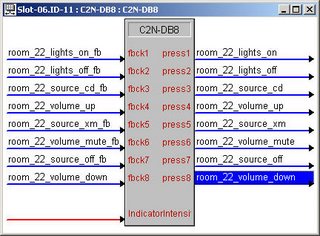
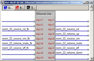
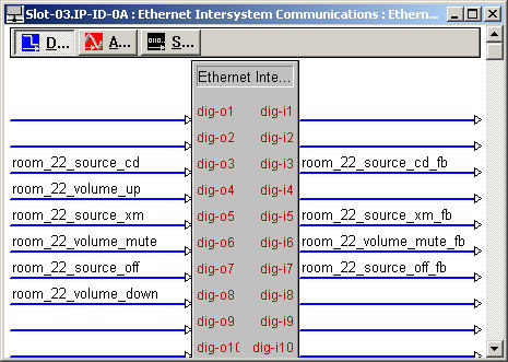
Drag the presses from the keypad to the dig-o signals on the Ethernet ISC in the PAC2 program. Drage the feedback to the dig-i signals. This will connect the signals so presses are sent out the Ethernet ISC, and feedback comes in from the Ethernet ISC. Note that for the buttons with momentary feedback, it is necessary to connect only the press. If you connect the feedback with the same momentary signal name as the press, you can create a loop and the signal will oscillate constantly.
Ethernet ISC Symbol in PAC2:
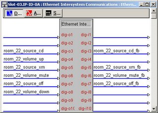
Now open the progam for the PRO2. The presses (which went into the dig-o signals on the Ethernet ISC in the PAC2) will come into this program on the dig-i. The outputs of one Ethernet ISC are connected to the inputs of the other, and vice versa. The feedback signals (which came out of the dig-i signals on the Ethernet ISC in the PRO2) will go into the dig-o signals on the Ethernet ISC in the PRO2 program.
Ethernet ISC Symbol in PRO2:
Upload and test! You should now be able to use the buttons on the PAC2 to control A/V logic in the PRO2.
This is a simple example, but the same procedure can be used to move analogs, serials, and digitals from touchpanels, keypads or logic back and forth between processors over Ethernet.
In our example, we will have a PAC2 processor that is used for lighting control, and a PRO2 processor that is used for audio/video control. The Cresnet network of the PAC2 processor will have some C2N-DB8 keypads, on which two buttons are used for lighting control (within the PAC2 program) and six buttons are used for selecting a source and controlling the volume for the audio system. Our PRO2 processor will be at 192.168.1.101, and our PAC2 will reside at 192.168.1.102.
The first step is to get the two processors onto the network, and test to confirm that they can communicate with one another. Assign each an IP address, and make sure you can ping one from the other. Use the Viewport or Toolbox command prompt command PING. (in our example: "ping 192.168.1.101" from the command prompt while connected to the PAC2 should reply "alive") If you can't ping the processors from one another, Ethernet ISC will not work.
Second, we will insert an Ethernet ISC definition underneath the network card in each processor. To do this, open the Configure view in SIMPL Windows, open the Network card, and double-click on an available IP-ID. Select Ethernet Intersystems Communications from the list. The two definitions must be at the same IP-ID in order for communications to be established. We will use the IP-ID 0A. Each processor's IP table entry will contain the IP address of the opposite processor. So, the PRO2 will have the PAC2's IP address (192.168.1.102) and the PAC2 will have the PRO2's IP address (192.168.1.101)
IP Table setup for PRO2:

IP Table setup for PAC2:
At this point we should upload our programs and check to make sure that Ethernet ISC connection is up. Be sure to upload both programs, and say YES to sending the default IP table. To check our Ethernet ISC, we can type EST at the command prompt in Viewport or Toolbox for a report of the current Ethernet status of the two Crestron processors. The IP-ID we are using (0A) should report ONLINE for both processors. If not, check the addresses in the IP table on both processors, check all of the network settings (IP address, subnet mask, gateway), any firewall (port 41794 needs to be open between the two) and the physical connections.
We are now ready to begin sending signals across our connection. We will need to send presses from the keypad in the PAC2 program to logic in the PRO2, and feedback from the PRO2 back to the keypad in the PAC2.
First, assign all of the signal names to the keypad as you normally would. Remember, our first two buttons are being used locally in the PAC2 for lighting control, so only buttons 3-8 are going to be connected to our Ethernet ISC.

Drag the presses from the keypad to the dig-o signals on the Ethernet ISC in the PAC2 program. Drage the feedback to the dig-i signals. This will connect the signals so presses are sent out the Ethernet ISC, and feedback comes in from the Ethernet ISC. Note that for the buttons with momentary feedback, it is necessary to connect only the press. If you connect the feedback with the same momentary signal name as the press, you can create a loop and the signal will oscillate constantly.
Ethernet ISC Symbol in PAC2:
Now open the progam for the PRO2. The presses (which went into the dig-o signals on the Ethernet ISC in the PAC2) will come into this program on the dig-i. The outputs of one Ethernet ISC are connected to the inputs of the other, and vice versa. The feedback signals (which came out of the dig-i signals on the Ethernet ISC in the PRO2) will go into the dig-o signals on the Ethernet ISC in the PRO2 program.
Ethernet ISC Symbol in PRO2:

Upload and test! You should now be able to use the buttons on the PAC2 to control A/V logic in the PRO2.
This is a simple example, but the same procedure can be used to move analogs, serials, and digitals from touchpanels, keypads or logic back and forth between processors over Ethernet.
posted by IP Wrangler at 8:32 AM
![]()
![]()
2 Comments:
No logro conectarme entre procesadores de diferentes redes, remotamente si puedo accesar pero no logro la comunicación entre ellos. hay alguna otra forma de comunicarlos??
Nice blog! I am truly awed by this blog! The photos are truly decent and cool.
InterSystems Technologies
Post a Comment
<< Home