Color-Changing Crestron Volume Control
One nice touch you can add to your Crestron touchpanel is a volume gauge that changes colors as you raise the level. This informs the user that the volume is getting close to the top limit. This also can be a visual "warning" to the user if they are switching from a source that doesn't have audio playing to a live source with the volume already at a high level.
In order to set up our color-changing volume control, we'll be using a multi-mode gauge on the touchpanel. This technique can be used for all other types of feedback, such as changing the text on borders or buttons, changing colors, etc.
To start, we need to set the threshold limits at which we want the gauge to change colors. In our example, we will have a gauge that is normally blue. It will change to yellow when the volume reaches 60%, and red when the volume reaches 85%. You can easily change these to your own values to best fit your application.
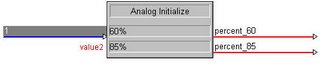
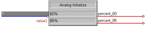
Insert an Analog Initialize (INIT) into your program. Place a 1 on the digital input, and expand the analog outputs (by pressing ALT and +) to two lines. Names these analog signals percent_60 and percent_85. In the parameter fields, enter 60% and 85% respectively.
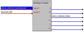
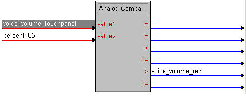
Next, insert an Analog Comparison (Full Set) (COMPARE2). This is a 2-series only symbol, but it is also much easier to understand than the original Analog Comparison. Value 1 should be the volume level (in this example it's "voice_volume_touchpanel"). Value 2 should be the signal "percent_85." The ">" or "greater than" signal will go high to indicate that the bar graph should be red. In this example, that signal is named "voice_volume_red" This will go high when Value 1 (the volume level) is greater than Value 2 (85%).

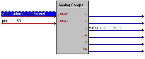
Now insert a second COMPARE2. This will determine when the volume level is below 60% and force a singal high indicating we want our normal (in this case blue) color for the gauge. We'll use the "<" or "less_than" output, which will go high when Value 1 (the volume level).
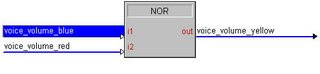
To determine when the gauge should turn yellow, we'll run the outputs of the other two singals through a NOR. If the gauge isn't blue or red, then it must be yellow!
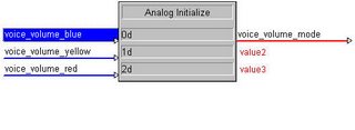
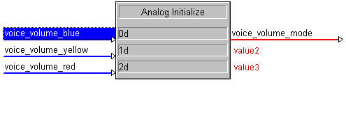
We'll now insert another Analog Initialize (INIT) into the program. This init will be used to set up the multi-mode gauge on the touchpanel. Each color will have its own state number (blue is state 0, yellow is state 1, and red is state 2). Run the analog output of your INIT to an analog join on your touchpanel. For our example, we'll use join number 2.
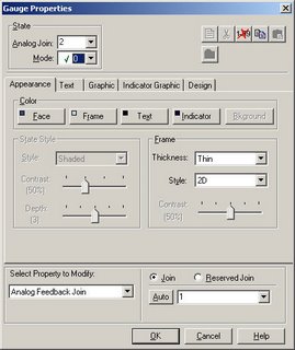
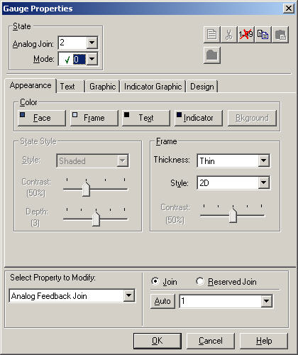
In Vision Tools, open the properties of your gauge. Assign the same Analog State join to the gauge that you used in SIMPL Windows. In this example, the join is 2. Set up your gauge for the "normal" mode (0) and then copy the mode by clicking the Copy Mode (looks like two piece of paper) button. Choose mode 1 from the drop down menu, click New Mode (looks like one piece of paper) button. Then click Paste Mode (looks like a clip board). Modify this to appear as you want for the "yellow" mode. Then repeat this process to set up mode 2 for the "red" mode.
You should be good to go! Your volume will now change colors as the volume increases.
In order to set up our color-changing volume control, we'll be using a multi-mode gauge on the touchpanel. This technique can be used for all other types of feedback, such as changing the text on borders or buttons, changing colors, etc.
To start, we need to set the threshold limits at which we want the gauge to change colors. In our example, we will have a gauge that is normally blue. It will change to yellow when the volume reaches 60%, and red when the volume reaches 85%. You can easily change these to your own values to best fit your application.
Insert an Analog Initialize (INIT) into your program. Place a 1 on the digital input, and expand the analog outputs (by pressing ALT and +) to two lines. Names these analog signals percent_60 and percent_85. In the parameter fields, enter 60% and 85% respectively.
Next, insert an Analog Comparison (Full Set) (COMPARE2). This is a 2-series only symbol, but it is also much easier to understand than the original Analog Comparison. Value 1 should be the volume level (in this example it's "voice_volume_touchpanel"). Value 2 should be the signal "percent_85." The ">" or "greater than" signal will go high to indicate that the bar graph should be red. In this example, that signal is named "voice_volume_red" This will go high when Value 1 (the volume level) is greater than Value 2 (85%).
Now insert a second COMPARE2. This will determine when the volume level is below 60% and force a singal high indicating we want our normal (in this case blue) color for the gauge. We'll use the "<" or "less_than" output, which will go high when Value 1 (the volume level).
To determine when the gauge should turn yellow, we'll run the outputs of the other two singals through a NOR. If the gauge isn't blue or red, then it must be yellow!

We'll now insert another Analog Initialize (INIT) into the program. This init will be used to set up the multi-mode gauge on the touchpanel. Each color will have its own state number (blue is state 0, yellow is state 1, and red is state 2). Run the analog output of your INIT to an analog join on your touchpanel. For our example, we'll use join number 2.
In Vision Tools, open the properties of your gauge. Assign the same Analog State join to the gauge that you used in SIMPL Windows. In this example, the join is 2. Set up your gauge for the "normal" mode (0) and then copy the mode by clicking the Copy Mode (looks like two piece of paper) button. Choose mode 1 from the drop down menu, click New Mode (looks like one piece of paper) button. Then click Paste Mode (looks like a clip board). Modify this to appear as you want for the "yellow" mode. Then repeat this process to set up mode 2 for the "red" mode.
You should be good to go! Your volume will now change colors as the volume increases.
posted by IP Wrangler at 6:29 PM
![]()
![]()
0 Comments:
Post a Comment
<< Home