Wednesday, June 28, 2006

Favorite Channels for Satellite or Cable TV

Let's talk about favorite channel logic. You've downloaded your television network logos from GuiFX's Freebie page, and you've added them to buttons in Vision Tools. Sure, you can easily insert a stepper into SIMPL Windows for each of the logos, but it's not very scalable. For instance, what if the client changes from DirecTV to Dish Network? You're going to open up dozens (or even hundreds?) of steppers and modify each one? And what if the new device requires different timing with the IR commands?

I'm sure this topic is one that will get some discussion going, because I'm pretty sure that almost every programmer has their own method for doing this. Here is what I usually do.

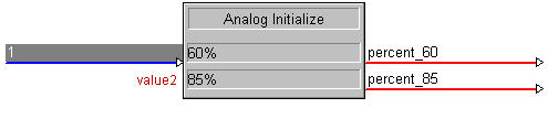
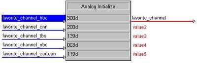
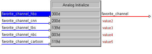
First, insert an Analog Initialize (INIT) into your program. The digital inputs will be the button presses, and the parameters will be the channel numbers in decimal. This is the only symbol you would need to edit if all of the channels changed, which makes it easy and scalable. We'll name the analog output "favorite_channel." If your program has more than one tuner, you'll want to be more specific, such as "living_room_cable_favorite_channel" or something like that. The more consistent you are with the signal names, the easier it will be to re-use your code later.


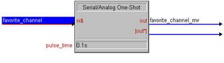
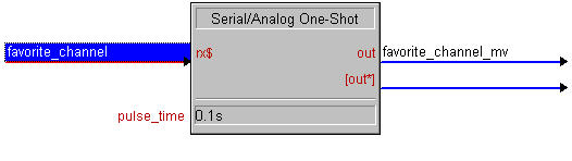
Second, insert a Serial/Analog One-Shot (AOS). This will be used to trigger the sequence when a new channel is selected. The AOS symbol take a Serial or Analog input, and pulses a digital whenever the input changes. We'll name the output "favorite_channel_mv." The _mv extension is a throwback to the Crestron Workshop days, when the One Shot symbol was called MV. Consider it tradition.


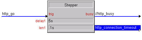
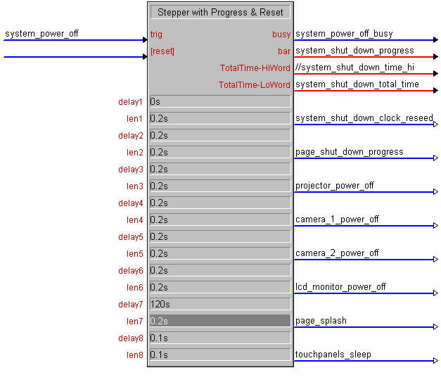
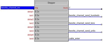
Third, insert a Stepper. This will contain the timing in which your IR signals will be sent. Again, if for some reason you need to speed up or slow down your IR commands, this is the only symbol you'll need to modify. The trigger is the output of our AOS. The busy is not needed and can be commented out. The outputs will be three digital signals to trigger the sending of the three digits (i.e. favorite_channel_send_hundreds, favorite_channel_send_tens, favorite_channel_send_units) followed by an enter command to the cable or satellite box. I tend to use delays of 0.2s and lengths of 0.3s as a starting point for IR devices. You can modify that based on the device you are using.


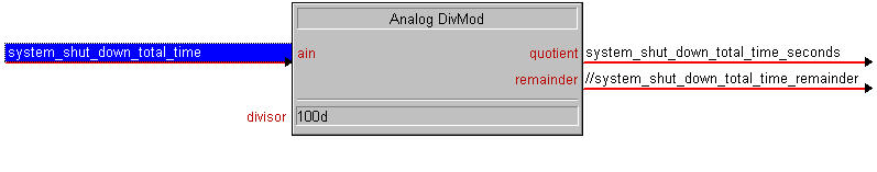
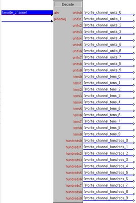
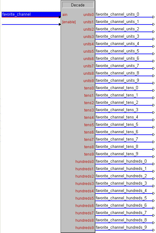
The next symbol is a Decade. This will "break down" the analog signal "favorite_channel" into a digital signal for each digit. (For example, if the analog signal fed into the decade is 562, the "hundreds5, tens6 and units2 outputs will be high)


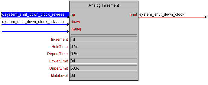
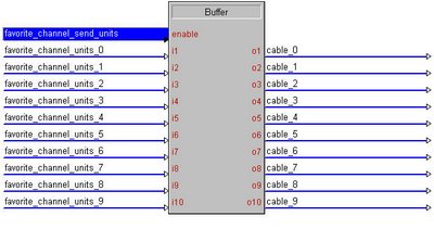
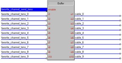
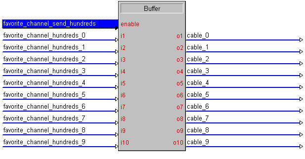
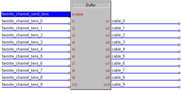
Now, insert a Buffer (BUF). Drag the "send_hundreds" signal to the enable, and the "hundreds" outputs from the Decade to the tens inputs. The outputs should contain the IR commands for the cable or satellite box.


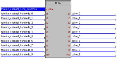
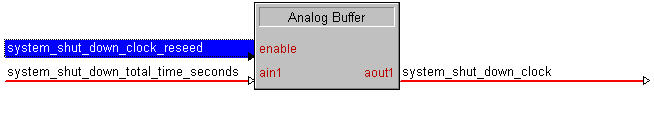
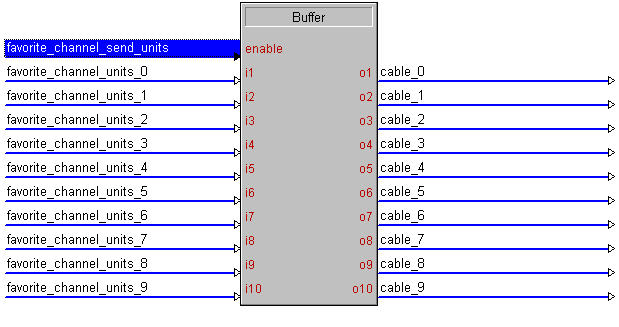
Copy the buffer using Ctrl-C and paste it twice using Ctrl-V. You should have three identical buffers. Select the second one down, press F9 (Search and Replace) and instruct SIMPL windows to replace "hundreds" with "tens" for Inputs and Comments. Repeat this on the third buffer, replacing "hundreds" with "units." This will save you some typing! See why it's important that all of our signal names are consistent?

Double check your search-and-replace (always double check any search-and-replace or auto-increment!). Your new buffers should look like this, and you should be ready to change channels. You can add as many inputs to the INIT as you want (go ahead and put every single Dish Network channel if you want!) and you'll only need these seven symbols to process it all.


Thursday, June 22, 2006

Requesting Content from a Web Page

In this example, we will demonstrate how to get the HTML source code of a web page into SIMPL Windows. This can be used for a wide variety of purposes, such as displaying information from the Internet on your touchpanel. I won't go into details about parsing the data from any particular site. Rather, I will provide you the information needed to get the HTML data into your program, and then you can do whatever you want with whatever web page you want.

This example is for an Ethernet equipped 2-series processor.

Before we begin, you must make sure you have DNS servers declared on your Crestron processor. DNS is how devices on the Internet resolve host names (like www.google.com) into IP addresses (like 64.233.167.99) Your Crestron processor will need to do this in order to connect with a web server.

At the text prompt in Viewport or Toolbox, type TESTDNS www.google.com. The processor should reply with an IP address. If it replies with 000.000.000.000, your DNS servers are not configured properly. You can add dns serverse by typing ADDDNS xxx.yyy.zzz.www. (Where xxx.yyy.zzz.www is the IP address of your DNS server) Typically you want to have two DNS servers if they are available.

If you don't know what your DNS servers are, open up a command prompt on a Windows computer using the same Internet connection as your Crestron processor. Type ipconfig/all. The DNS servers will be listed on the last few lines of the output.

Once you have your Crestron processor set up to resolve host names using DNS, you are ready to get to work in SIMPL Windows. We will begin in the configuration view by adding a TCP/IP client to an unused IP ID of your Ethernet card. Open up the properties for this TCP/IP client and select the IP Net Address tab. Underneath "Default Address," check "Use Host Name" and enter the hostname of the website you want to download. In our example, we will download the content of the page www.google.com. If you are trying to reach a page other than the index (such as http://www.google.com/intl/en/about.html) you would still enter only www.google.com here. This field is used only to resolve the IP address of the server on which the content is hosted.


Switch back to the programming view of SIMPL Windows. Open the TCP/IP client. Enter the port number (usually 80) in the port field. The "connect" digital input will tell the TCP/IP client to open a session. We'll name this signal "connect_http." We'll also need to know the status of the connection from the analog output, which we'll name "http_status." The traffic being sent by the Crestron processor to the web server will go out the tx$ (http_tx$). The traffic coming back from the web server will come in on the rx$ (http_rx$). This is what you will parse to get any information you want from the web server.


We'll now set up logic to timeout the connection if it is open too long. The web server will drop your connection automatically at the end of a successful download, but if things don't go well, we want the Crestron processor to drop the connection itself after 5 seconds. Insert a Stepper into your program. The trigger should be "http_go." This will be the signal you pulse when you want the program to retrieve data. The busy is not needed and can be commented out. The only step needed (delay 5s, length 0.1s) is "http_connection_timeout."


Next insert an Analog Equate (EQU) into the program. This will take the analog signal "http_status" and decode it into digital signals containing the status of the TCP/IP connection. Most of these can be commented out... The only ones we need are connected, connection_failed and connection_broken_locally.


We now have three different things that would necessitate the Crestron processor to drop the TCP/IP connection: If the connection fails, if it is broken remotely, or if it times out. Insert an OR and run these three signals to the input. The output will be a new signal, "http_disconnect."


We need a signal to be held high for the connection process. We'll use a Set/Reset Latch (SR). The "set" signal will be "http_go" (the same signal that starts our stepper). The "disconnect" signal will be "http_disconnect" which is generated by our disconnect logic.


Finally, we need to send a properly formatted HTTP GET request. The syntax of this is very important. Insert a Serial Send (SEND) into your program. The trigger will be "http_status_connected" (which will trigger the string to send once the TCP/IP client reports a successful connection) and the tx$ will be http_tx$. The string must be exactly as follows:

GET / HTTP/1.0\nHost: www.google.com\n\n

Replace www.google.com with the name of the website you are trying to connect to. If you are connecting to a page other than the index, you would replace the first / with the path to the files.) For example, to reach http://www.google.com/intl/en/about.html, your string would be as follows:

GET /intl/en/about.html HTTP/1.0\nHost: www.google.com\n\n


Upload to your processor (be sure to send the IP table when you do!) and pulse http_go. You will see the content of the web site coming in on http_rx$.

(Thanks to Chip Moody for suggestions cleaning up the logic that triggers the "GET" request)

Wednesday, June 21, 2006

Color-Changing Crestron Volume Control

One nice touch you can add to your Crestron touchpanel is a volume gauge that changes colors as you raise the level. This informs the user that the volume is getting close to the top limit. This also can be a visual "warning" to the user if they are switching from a source that doesn't have audio playing to a live source with the volume already at a high level.

In order to set up our color-changing volume control, we'll be using a multi-mode gauge on the touchpanel. This technique can be used for all other types of feedback, such as changing the text on borders or buttons, changing colors, etc.

To start, we need to set the threshold limits at which we want the gauge to change colors. In our example, we will have a gauge that is normally blue. It will change to yellow when the volume reaches 60%, and red when the volume reaches 85%. You can easily change these to your own values to best fit your application.

Insert an Analog Initialize (INIT) into your program. Place a 1 on the digital input, and expand the analog outputs (by pressing ALT and +) to two lines. Names these analog signals percent_60 and percent_85. In the parameter fields, enter 60% and 85% respectively.


Next, insert an Analog Comparison (Full Set) (COMPARE2). This is a 2-series only symbol, but it is also much easier to understand than the original Analog Comparison. Value 1 should be the volume level (in this example it's "voice_volume_touchpanel"). Value 2 should be the signal "percent_85." The ">" or "greater than" signal will go high to indicate that the bar graph should be red. In this example, that signal is named "voice_volume_red" This will go high when Value 1 (the volume level) is greater than Value 2 (85%).


Now insert a second COMPARE2. This will determine when the volume level is below 60% and force a singal high indicating we want our normal (in this case blue) color for the gauge. We'll use the "<" or "less_than" output, which will go high when Value 1 (the volume level).


To determine when the gauge should turn yellow, we'll run the outputs of the other two singals through a NOR. If the gauge isn't blue or red, then it must be yellow!


We'll now insert another Analog Initialize (INIT) into the program. This init will be used to set up the multi-mode gauge on the touchpanel. Each color will have its own state number (blue is state 0, yellow is state 1, and red is state 2). Run the analog output of your INIT to an analog join on your touchpanel. For our example, we'll use join number 2.


In Vision Tools, open the properties of your gauge. Assign the same Analog State join to the gauge that you used in SIMPL Windows. In this example, the join is 2. Set up your gauge for the "normal" mode (0) and then copy the mode by clicking the Copy Mode (looks like two piece of paper) button. Choose mode 1 from the drop down menu, click New Mode (looks like one piece of paper) button. Then click Paste Mode (looks like a clip board). Modify this to appear as you want for the "yellow" mode. Then repeat this process to set up mode 2 for the "red" mode.


You should be good to go! Your volume will now change colors as the volume increases.

InfoComm Roadmap to Control

Ever work with a device that had a control protocol that made things more difficult than they needed to be? Of course, we all have.

InfoComm International
recently launched a document called the Roadmap to Control. This document provides recommendations to equipment manufacturers on the implementation and documentation of RS-232 and TCP/IP control protocols.

If this is something you're interested in, read the document and provide comments on the suggestions. Or, email a copy to the equipment manufacturers you deal with, and encourage them to implement the suggestions in their products.

Monday, June 19, 2006

Crestron Touch the PC

You can use an RGB-capable Crestron TPS series touchpanel as a touch screen for a PC. In order to do this, you must implement a feature called "Touch the PC."

First, create a touchpanel project in Vision tools.

Right click on the panel in the tree structure and select Properties. On the Pad Area tab, select "Touch the PC v2" and "Serial" as the connection type for one of the two Pads.


Now create an RGB window. It probably only makes sense for this to be a full screen RGB window, since you will be using it as a computer monitor and your finger as a mouse. Open the RGB properties, and select the Pad Area you set up previously on the Design tab.


Connect a serial cable between the TPS touchpanel and the PC. This cable should be constructed to the following pinout:


In the touchpanel Interface setup menu, select "RS-232 Port for Touch Output"

On the PC, you must install the Crestron Serial Mouse Control driver. At this point, it is located on the Crestron FTP server in the /firmware/serial_mouse_control_driver/ directory. The current version is serial_mouse_control_driver_3.08.34p.zip. You must also then use the software on the PC to calibrate the driver.

Wednesday, June 14, 2006

Start Up or Shut Down "Time Remaining"

This example will allow you to put a Timer object on your Crestron touchpanel that displays the time remaining in a Stepper sequence. This is useful for a startup or shutdown "time remaining" indicator. This example is for a 2-series processor. As always, no SIMPL+ is required.

This logic is all fully scalable. As you insert new logic into your stepper, all of the values will be dynamically recalculated. This logic works for any sequence shorter than 600 seconds (ten minutes). If your sequence is longer, you'll need to use the time hi-word and do some additional math.

1. The first step is to insert a Stepper with Progress & Reset (STEPPER2) symbol. Populate the delays, lengths, and outputs with all of the events for your sequence. In this example, it is a shut down sequence. If you need to "pad out" some time at the end (i.e. waiting for a projector to power down) just insert a dummy step with the amount of time necessary.

You will need the busy signal, the bar output, and the time loword. You can comment out the time hiword, since we are limiting our logic to 600 seconds or less. You also need the first step to be a "reseed" step, which we will use to reset our countdown clock later on.


2. We need to scale the time down from 1/100ths of seconds to just regular seconds. We'll use an Analog DivMod (DIVMOD) symbol to do this. Take the total time loword value from your Stepper2, and tie it to the input of a DivMod. The divisor will be 100d, since we need to divide by 100. The quotient will be the number of seconds your entire countdown sequence will take. The remainder can be commented out.


3. The next step is to setup a trigger to advance the clock as the stepper runs. We'll use an oscillator (OSC) for this. The trigger is the busy signal from the Stepper2. The output signal will be used to advance the clock. The hi_time should be 0.1s, and the lo_time 0.9s.


4. We'll now insert our logic to actually modify our clock. We'll use an Analog Increment (AINC). The up input is not needed and can be commented out. The down input will be trigger by the output of our Oscillator. The output is the analog signal for our countdown timer on the touchpanel. Tie this to your touchpanel, and create a Timer object in Vision Tools.


5. Finally, we need logic to set the clock to the beginning value when our countdown begins. An Analog Buffer (ABUF) should be inserted. The enable will be the reseed value from the first step of our Stepper2. The input is the total time in seconds that is provided by our DivMod. The output will be the actual countdown analog signal. This is the same signal that is on the output of the Increment, and is tied to the touchpanel's timer object. The increment is 1d, because we want the timer to advance by one second at a time. The hold time and repeat time really aren't important, so set them to 0.5s each. The lower limit is 0d, and the upper limit is 600d (because the only values our timer will display are between 0 seconds and 600 seconds (10 minutes)). The mute level is also not important and can be set to 0d.